








Sintered NdFeB small neodymium magnets
Sintered NdFeB small neodymium magnets are made from a combination of various raw materials to achieve their magnetic properties. The primary elements in the composition of sintered NdFeB magnets include neodymium (Nd), iron (Fe), and boron (B). Additionally, other elements such as dysprosium (Dy) or praseodymium (Pr) may be added to improve the magnets’ performance, particularly in high-temperature applications or to enhance resistance to demagnetization.
We all know that the main raw materials of sintered NdFeB permanent small neodymium magnets are neodymium, iron and boron, but in addition, many other elements are added to the raw materials, and these elements play different roles in the magnets. , manufacturers often design product formulas based on user needs. The raw material formula can be said to be the top secret information of each manufacturer.
The more than ten elements of sintered NdFeB are just like the various seasonings we need to add to make a delicacy. It is precisely because of the scientific and regular combination of these elements with different intrinsic properties and functions that our NdFeB is made. Boron comes in a variety of different grades and properties. Understanding the meaning of each element is of great significance for us to better understand the performance and manufacturing costs of different grades. Below we briefly introduce the value of these elements.
For easier understanding, we can divide the constituent elements of NdFeB into three categories:
◇ One is the main elements RE (Ce, Gd, Nd, Dy, etc.), Fe, B, which are mainly responsible for forming RE2Fe14B main phase grains.
◇ The second is small elements such as Al, Co, Ga, and Zr, which are mainly responsible for optimizing the coating of grain boundaries relative to main phase grains.
◇ Third, impurity elements, such as carbon, oxygen, etc., are inevitably introduced into raw materials and production.
A schematic diagram of the types of NdFeB elements is shown in the figure below.

Actual raw material manufacturers often have certain deviations due to different process routes used in the production process. For example, the ratio of PrNd will change from 20:80 to 25:75, GdFe will appear less than 75%, and B in different batches of BFe The content will fluctuate greatly, which requires us to use it in proportion to the actual content of each batch of quality inspection documents during use.
Each element contained in NdFeB small neodymium magnets has its own unique characteristics, such as:
◇ The introduction of La and Ce elements will reduce the remanence Br and coercive force Hcj of the magnet, but its price is very cheap and can reduce costs;
◇ REFeB composed of pure Nd element replacing PrNd has very high saturation magnetization and can be used to prepare ultra-high remanence magnets;
◇ The introduction of Tb element can greatly improve the Hcj of the magnet, but its cost is extremely expensive;
◇ The Gd element is relatively cheap. The REFeB formed by it has the highest Curie temperature and can prepare high-temperature resistant magnets, but it will significantly reduce Br.
In order to figure out how to combine to produce a magnet with the required performance at the lowest cost, we need to understand the characteristics of each element in NdFeB small neodymium magnets.
More than 80%-90% of the material cost is mainly composed of the “high and low” part of the note, where the “—” part indicates that the amount of addition is very small or the price is cheap, which has little impact on the overall cost small neodymium magnets. Among them, La and Ce are added mainly to reduce costs. In recent years, with the continuous advancement of technology, Ce magnets have been used in more and more higher grades.
By deeply understanding the characteristics of the above elements and understanding the impact of various elements on the sintering process, sintering density, aging process, and product performance, we can guide us to produce NdFeB small neodymium magnets products with higher cost performance.

The magnetic field is invisible and intangible, so how to draw the shape of the magnetic field and describe the direction of the magnetic field? Finite element simulation is a great way to do this.
Finite element simulation, also called FEA simulation (Finite Element Analysis), uses computers to simulate real physical systems using complex mathematical equations, models and formulas.
Using simple and interacting elements (i.e. units), a limited number of The unknown quantity is used to approximate the real system with infinite unknown quantity. It has been widely used in the fields of temperature field, electric field small neodymium magnets, magnetic field, force field, seepage field, acoustic wave field and other fields. Commonly used magnetic field simulation software includes ANSYS, ABAQUS, Comsol Multiphysics, JMAG-Designer, and EasiMotor.

It is relatively difficult to get started with simulation software. In addition to overcoming the problems in using the new software, you also need to understand the magnetic parameters of different materials in the material library. And because magnetic field simulation is relatively niche small neodymium magnets, almost all permanent magnet materials and soft materials in the software material library Magnetic materials are not complete, and it also involves the possibility of establishing new materials.
How to establish the magnetic parameters and demagnetization curves of new materials. These all need to be based on a thorough understanding of the material itself and the basic knowledge of magnetism.
Different FEA software may have different usage techniques small neodymium magnets. This article uses ANSYS software as an example to introduce the common steps for finite element simulation of permanent magnet magnetic fields:
1. Select the design type. ANSYS software has many design modules. Even the specialized electromagnetic field design module also includes design modules for high frequency, electric field, circuit, and static magnetic field. The static magnetic field module is usually selected for surface magnetic simulation small neodymium magnets.
2. Modeling. Similar to 2D 3D modeling, draw the shape, position, and test points of the magnets that need to be simulated. Models can also be imported via 2D and 3D drawing software.
3. Add materials. All materials must have material properties defined, otherwise they will default to vacuum or run errors will occur. It should be noted here that permanent magnets need to define the magnetization direction, and the magnetization direction is generally defined based on the coordinate system.
4. Set the calculation domain. A suitable computational domain is critical. If you do not set a computational domain, it will default to the entire space being a computational domain small neodymium magnets. Although this is consistent with the actual situation, because there may indeed be no other interfering substances around the magnet, this will lead to a large error in the calculation results. And the operation is time-consuming.
5. Set boundary conditions. Setting boundaries is to match the settings of the calculation domain and reduce the complexity of the problem. Setting reasonable boundaries can help us save a lot of time in calculations. Different boundaries have different meanings. Usually we choose balloon boundaries for static magnetic field simulations. .
6. Set the incentive source. When the selected material is a permanent magnet, the system will automatically help us select magnetostatic excitation. If we need to simulate the coil magnetic field, we need to add voltage or current as the excitation source.
7. Divide the grid. Meshing simply means connecting these finite element calculations to create a mesh structure. The software comes with meshing. The denser the mesh structure, the more accurate the results will be and the more time-consuming it will be.
8. Add solution settings. Here you can set the error rate and number of calculation steps, and the system also comes with default settings.
9. Add solution operation. That is what result you want this simulation to help you get, whether it is to look at the direction of the magnetic field lines or the magnetic field data.
10. Post-processing. After the simulation is completed, you can view the magnetic field line diagram (scalar or vector), various cloud diagrams, the data and parameters set at the beginning of the period that need to be simulated, etc.
A permanent magnet creates a magnetic field around itself due to the alignment of its magnetic domains within the material small neodymium magnets. This magnetic field extends from the magnet in all directions and is characterized by its strength and direction.
The strength of the magnetic field produced by a permanent magnet depends on factors such as the material composition, the shape and size of the magnet, and the magnetization process it undergoes.
Near the surface of a permanent magnet, the magnetic field is typically stronger, and it gradually weakens as you move away from the magnet. The strength of the magnetic field decreases with distance according to the inverse square law small neodymium magnets, which states that the strength of the magnetic field decreases with the square of the distance from the magnet.
The magnetic field produced by a permanent magnet has both magnitude and direction. The direction of the magnetic field lines is defined to be the direction that the north pole of a compass needle would point if placed in the field small neodymium magnets. The field lines extend from the north pole of the magnet to the south pole, forming closed loops outside the magnet.
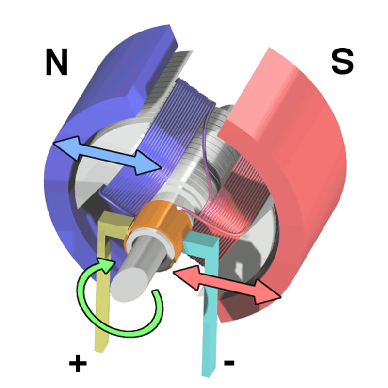
Permanent magnets are used in a wide range of applications, including electric motors, generators, magnetic resonance imaging (MRI) machines, magnetic separation, sensors, and many others small neodymium magnets, due to their ability to produce a stable and persistent magnetic field without the need for an external power source.