




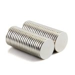
Large Ferrite Ring Magnets
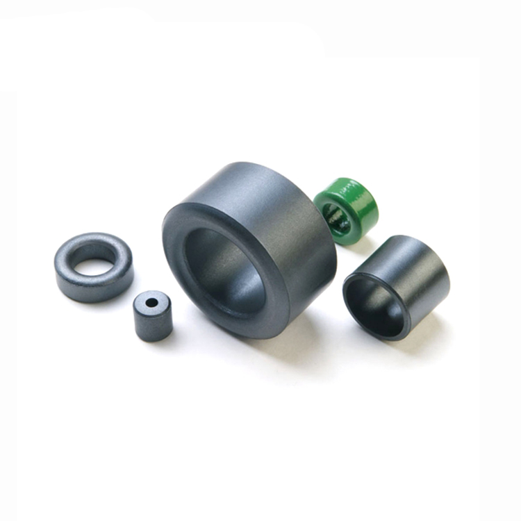
Large ferrite ring magnets are also commonly used in various applications, although they are not as strong as neodymium magnets. Ferrite magnets, also known as ceramic magnets, are made from a combination of iron oxide and other metallic elements.
Here are some applications where large ferrite ring magnets are used:
Speakers: large ferrite ring magnets are often found in loudspeakers, where they create a magnetic field that interacts with the voice coil to produce sound.
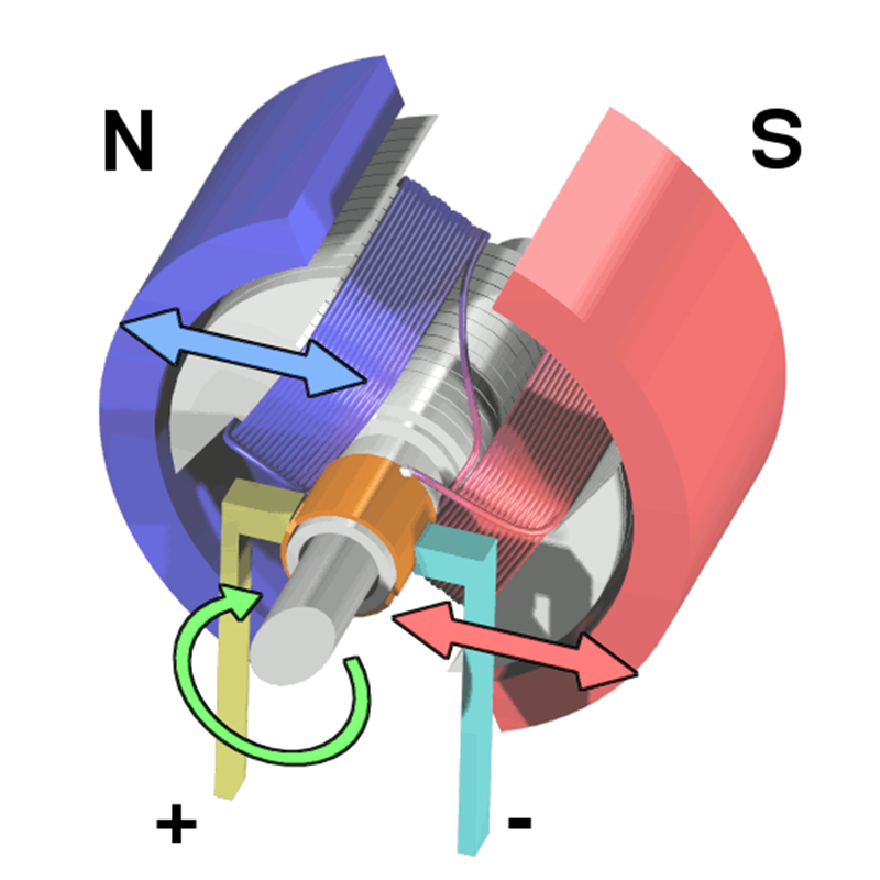
Electric Motors and Generators: They are used in electric motors and generators for various industrial and household applications, such as fans, pumps, and appliances.
Magnetic Couplings: Ferrite ring magnets can be used in magnetic couplings to transmit torque between two rotating shafts without physical contact, commonly used in pumps and mixers.
Magnetic Separators: Large ferrite ring magnets can also be used in magnetic separators to remove ferrous contaminants from materials such as food, chemicals, and minerals.
MRI Machines (for low-field MRI): While not as common as neodymium magnets in high-field MRI machines, ferrite magnets are used in some low-field MRI machines for medical imaging.
Water Treatment Systems: They are used in water treatment systems to remove iron and other contaminants from water.
large ferrite ring magnets are generally more affordable than neodymium magnets and have good resistance to demagnetization, but they are also significantly less powerful. However, they are still suitable for many applications where high magnetic strength is not required.
Magnetic moment and magnetic flux: can be converted by coil constant
Magnetic moment is an important parameter that describes the magnetic strength of ferromagnetic materials, especially permanent magnet materials. The open-circuit magnetic moment is one of the factory qualification indicators of finished permanent large ferrite ring magnets. The domestic permanent magnet industry uses the pull-out method to measure the magnetic moment. Generally, another important use of using this method to measure magnetic moment is to sample the uniformity of large permanent magnets.
This test is basically required for permanent large ferrite ring magnets used in wind power generation and electric vehicles. Our country has formulated the standard GB3217-2013 for measuring the closed magnetic circuit magnetism of permanent magnet materials, but there is no relevant method standard for open circuit magnetic moment measurement that applies to the above requirements.
The current international standard is IEC60404-14 (pulling or rotating Method for testing the magnetic dipole moment of ferromagnetic materials), and my country is already formulating similar standards.
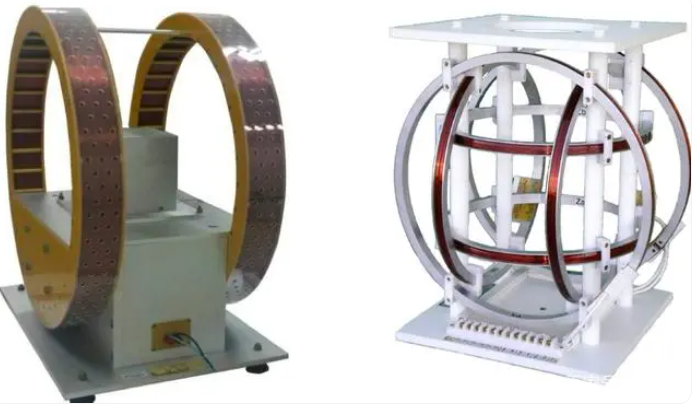
By measuring the open-circuit sample in a Helmholtz coil with a strictly calibrated coil constant of k, the magnetic flux value can be obtained, and the magnetic moment M of the material can be calculated from the magnetic flux value.
The calculation formula for measuring the magnetic moment of a magnet using a fluxmeter and a Helmholtz coil is as follows:
M = k * Ф, where
M represents the magnetic moment of the magnet, the unit is Wb·cm-1
k represents the coil constant, unit: cm-1 (a unit change in the coil constant will cause a change in the magnetic moment unit)
Ф represents the magnetic flux value, unit: Wb
We need to remind everyone that in the process of production and trading, it is very common to measure the magnetic moment of finished products or permanent magnets with special shapes by pulling the coil under open circuit. However, companies generally build their own measuring devices and receive coils. Affected by various factors such as calibration and operating techniques, the measurement reproducibility is poor.
The calibration of the test coil requires passing a steady current in a zero magnetic field environment to test the magnetic field size, and then obtain the constants of the test coil. However, there are only a handful of truly zero-magnetic field laboratories around the world, so the calibration of test coils is difficult to promote in the industry. The lack of calibration of test coils will directly affect the accuracy and reliability of the test, which may in turn bring about some trade dispute.
Magnetic moment and remanence: have a functional relationship and are closely related to the size of the large ferrite ring magnets.
When the magnetic flux or magnetic moment of the large ferrite ring magnets is known, if the shape and size of the magnet are known, the Br, HcB and (BH)max values of the magnet can be obtained by calculating the permeability coefficient Pc of the permanent magnet material; and vice versa. However, given the shape, dimensions and remanence, the magnetic moment of the magnet can be calculated.
Magnetic permeability coefficient Pc
The permanent large ferrite ring magnets works in an open circuit state. Since the magnet in the open circuit state is under the action of the demagnetization field, the magnetic induction intensity of the permanent magnet in the working state is not at the Br point in the closed circuit state, but at a demagnetization curve lower than Br. A certain point on the magnet is called the operating point of the permanent magnet, such as point D in the figure above.
The working point is related to the shape of the demagnetization curve and the size of the demagnetization field of the magnet under working conditions. The straight line connecting the operating point D and the origin O is called the load line. Its slope is related to the demagnetization factor of the magnet. The slope of the load line is also called the magnetic permeability, represented by Pc (permeance coefficient).
Pc=BD/ HD=μ0(1-1/N) or Pc=1-4π/N
The demagnetization factor is closely related to the geometric shape of the large ferrite ring magnets, so the size of the Pc value is closely related to the shape and size of the magnet. The more slender the magnetization direction, the smaller the demagnetization factor. The flatter the magnetization, the larger the demagnetization factor. 0< N<1 or 0<N<4π.

Given the size and remanence of sintered large ferrite ring magnets, how to calculate the magnetic moment and flux?
1·Calculate the volume and Pc value of the magnet based on its shape and size
2· Calculate Bdi based on the relationship between Br and Bdi

Note: Bdi refers to the intrinsic flux density, and the recovery permeability μrec=Br/HcB (sintered NdFeB commonly used 1.05 as an estimated value)
3· According to Bdi=magnetic moment/volume, calculate the magnetic moment of the magnet backwards
4. According to the magnetic moment M = k * Ф, the magnetic flux Ф can be simulated and calculated when the coil constant k is determined.
Please note:
The magnetic moment calculated according to the above method is an estimated theoretical value, which is often different from the actual measured value. This is affected by the crystal structure of the magnet itself, as well as the influence of the external environment and the test coil large ferrite ring magnets.
You can search for some magnetic moment calculators or calculation models on the Internet. In most of these calculators, the recovery magnetic permeability μrec is set to 1.05, which is not calculated using the remanence and coercive force of the magnet itself large ferrite ring magnets. Therefore, it is calculated The magnetic moment can only be used as a reference.
The concepts of magnetic moment and flux are fundamental to understanding the behavior of magnets, including ferrite and large ferrite ring magnets.
Magnetic Moment:
Magnetic Moment (μ) refers to the measure of the strength and orientation of a magnet’s magnetic field. It is a vector quantity, indicating both the strength and direction of the magnet’s poles.
For a bar magnet, the magnetic moment points from the magnet’s south pole to its north pole.
In terms of its physical properties, the magnetic moment is related to the product of the magnet’s pole strength and the distance between the poles.
Flux:
Flux (Φ) refers to the total magnetic field passing through a surface. It is a scalar quantity and represents the total magnetic field lines penetrating a given area.
Magnetic flux is measured in Weber (Wb).
Now, onto the relationship between magnetic moment and remanence large ferrite ring magnets:
Magnetic Moment and Remanence:
Remanence is a property of a magnet, representing the residual magnetic induction remaining in the material when the magnetizing field is removed.
Magnetic moment and remanence are related but not directly proportional. Remanence is more closely related to the magnet’s ability to retain its magnetization when the external magnetic field is removed.
For a magnet, when it is magnetized in a particular direction, it has a certain magnetic moment. Remanence refers to how much of that magnetic moment remains after the magnetizing force is removed.
In the context of neodymium and ferrite magnets:
Neodymium magnets typically have higher remanence compared to ferrite magnets, meaning they retain more of their magnetization after being magnetized.
Neodymium magnets generally have higher magnetic moments compared to ferrite magnets due to their stronger magnetic fields large ferrite ring magnets.
So, while magnetic moment represents the strength of the magnet’s magnetic field, remanence indicates how much of that magnetic moment is retained when the external magnetic field is removed.
1. Static demagnetization
Add a magnetic field opposite to the original magnetization direction of the magnet. The strength of this reverse magnetic field should ensure that when it is removed, the magnetic induction intensity of the magnetic body becomes zero. The resulting magnetically neutral state is called the static magnetically neutral state.
In the hysteresis curve, the red line segment in the second quadrant represents the demagnetization curve, that is, when a magnet is applied with a magnetic field opposite to the magnetization direction large ferrite ring magnets, its magnetic induction intensity decreases as the reverse magnetizing field intensity increases. When the magnetizing field strength reaches -Hc, the magnetic induction intensity of the magnet drops to 0, and the magnet is no longer magnetic.
The hysteresis loop is measured at room temperature. When the magnet demagnetizes at different operating temperatures, the demagnetization curves are different, as shown in the figure below. Therefore, the reverse magnetic field intensity applied for demagnetization under different temperature conditions is different.
(Pictures come from the Internet)
2. Dynamic demagnetization
Apply a strong enough alternating magnetic field to the magnetic body, and then gradually reduce the amplitude of the alternating magnetic field to 0. The resulting magnetically neutral state is called the dynamic magnetically neutral state.
The principle of this method is to place the workpiece in an alternating magnetic field and use the hysteresis loop to demagnetize. As the amplitude of the alternating magnetic field gradually decays, the trajectory of the hysteresis loop becomes smaller and smaller. When the magnetic field gradually decays to zero, the residual magnetism in the workpiece will be close to zero.
The demagnetization principle is shown in the figure below. It can be seen from this that the changes in the direction and magnitude of the current and magnetic field during demagnetization must be commutated and attenuated at the same time.
(1) AC demagnetization
The workpiece that has been electromagneticized by AC is demagnetized by AC, and the pass method or the attenuation method can be used.
For batch demagnetization of small and medium-sized workpieces, it is best to place the workpieces on a demagnetization machine equipped with tracks and carriages. During demagnetization, place the workpieces on the carriage 30cm in front of the coil large ferrite ring magnets. When the coil is energized, move the workpieces along the The track passes slowly through the coil and is de-energized at least 1m away from the coil. For heavy or large workpieces that cannot be placed on the demagnetizer for demagnetization, you can also put the coil on the workpiece. When the power is on, slowly pass the coil and keep it away from the workpiece, and cut off the power at least 1m away.