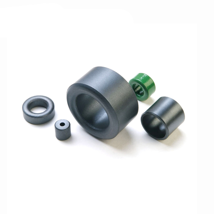
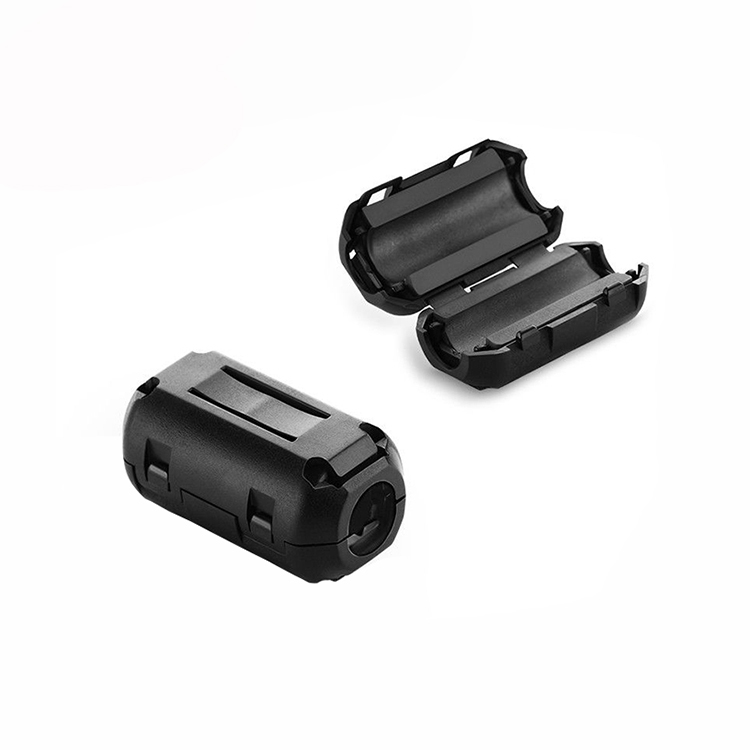
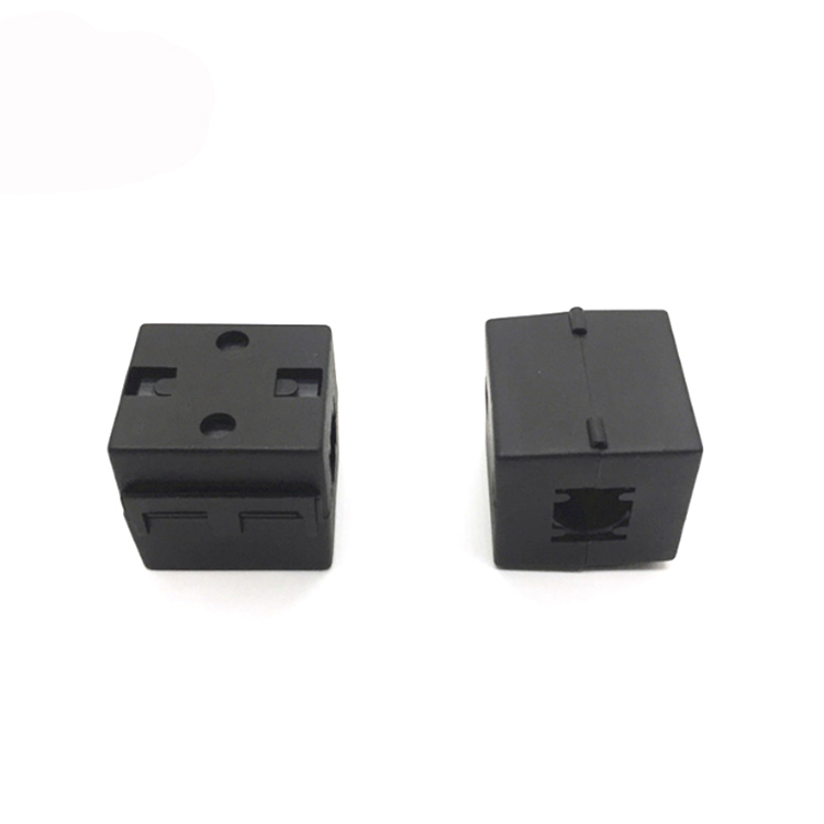
A ferrite core is what?
A magnet with a ferrite center is made especially to lessen electromagnetic interference. As a result, ferrite centers are excellent at minimizing wireless interference brought on by electrical noise.
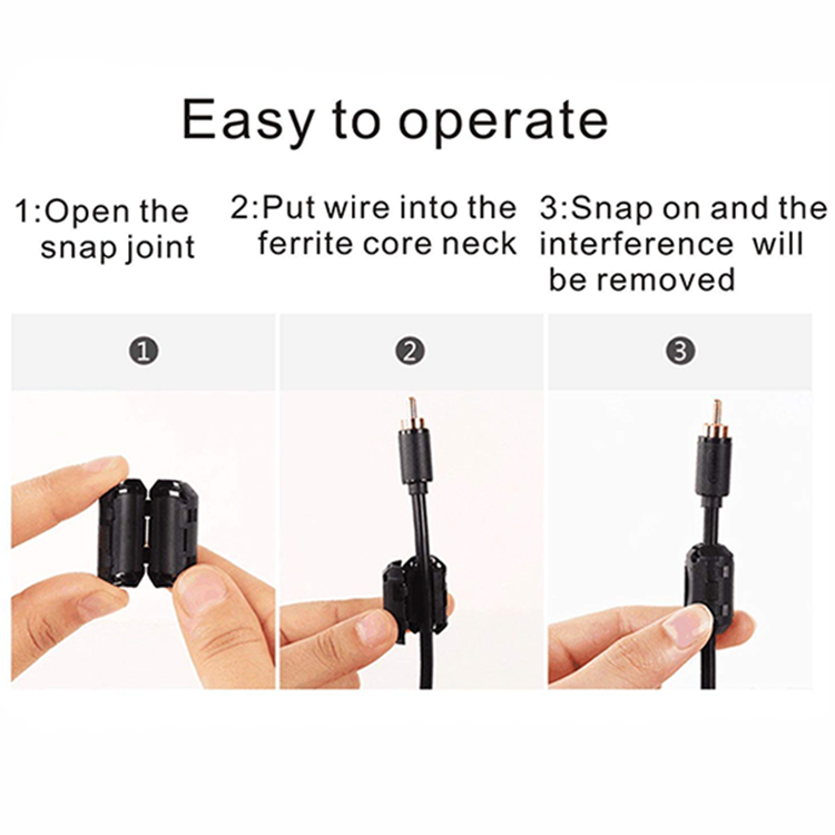
A ferrite core installation guide
A loop in the wire that passes through the magnetic field, loops around, and then passes back through must be fitted with a ferrite core for the installation to be effective. Kindly review the sample provided below. We advise positioning the center about 15.2 centimeters (6 inches) away from the dash cam itself.
How to proceed if a ferrite core is installed but wireless disturbance persists
The cable(s) for your dash camera may be channeled close to the aerial; try rerouting them away from their present location.
A ferrite core is what?
A magnet with a ferrite center is made especially to lessen electromagnetic interference. As a result, ferrite centers are excellent at minimizing wireless interference brought on by electrical noise.
A ferrite core installation guide
A loop in the wire that passes through the magnetic field, loops around, and then passes back through must be fitted with a ferrite core for the installation to be effective. Kindly review the sample provided below. We advise positioning the center about 15.2 centimeters (6 inches) away from the dash cam itself.
How to proceed if a ferrite core is installed but wireless disturbance persists
The cable(s) for your dash camera may be channeled close to the aerial; try rerouting them away from their present location.
Shield cores (RH series) and Toroidal cores (T series) are ring-shaped EMI suppression cores used to reduce high frequency noise from cables. RH cores are commonly utilized in cable construction using plastic injection molding. Smaller RH cores are typically utilized to pass through other element beads or to act as inductors by passing through wire. T cores are mostly utilized for EMI reduction in common mode or differential mode filters. If the design necessitates a greater impedance, increasing the wire turns through the core is a quick and simple solution.
An EMI filter is also known as a Ferrite Choke, Ferrite Bead, Ferrite Block, or Ferrite Ring.
Watch as I attempt to explain how ferrite cores function without delving into the mechanics of the electromagnetic spectrum and nuclear forces. Ferrite cores operate by blocking electromagnetic interference in both ways, shielding the connection from outside interference while also preventing the cable from producing signals. Any cable that contains any type of metal (almost any cable) will function as an antenna. If the devices to which you’ve connected your cable create RFI or EMI (nearly any electronic equipment), the cable will transmit and emit these signals as noise in addition to the signal they’re supposed to send.
Furthermore, if there is RFI or EMI in the cable’s vicinity, such as other electronic household equipment, the cable will behave as an antenna, receiving these undesirable signals. Because ferrite cores are both conductive and magnetic, they concentrate electromagnetic impulses and dissipate them as heat. Don’t worry, they’re not heated!
Having stated that, many cables these days are already capable of handling undesired RFI or EMI. They’re typically well-made, protected (at least mine are), and built to withstand the conditions they’ll face. However, cables are occasionally utilized in situations where they are stretched to their limitations, most notably when excessively long cables are employed in place of more normal lengths.
A ferrite core can assist enhance signal quality in certain instances. Grab a pair of cores for a lengthy TV antenna connection or USB cable, for example; if you’re experiencing weak signal or dropouts, the cores should make an instant impact. Additionally, if your sensitive AV equipment, such as in a home theater, is picking up noise, placing ferrite cores on your cables may help minimize it!
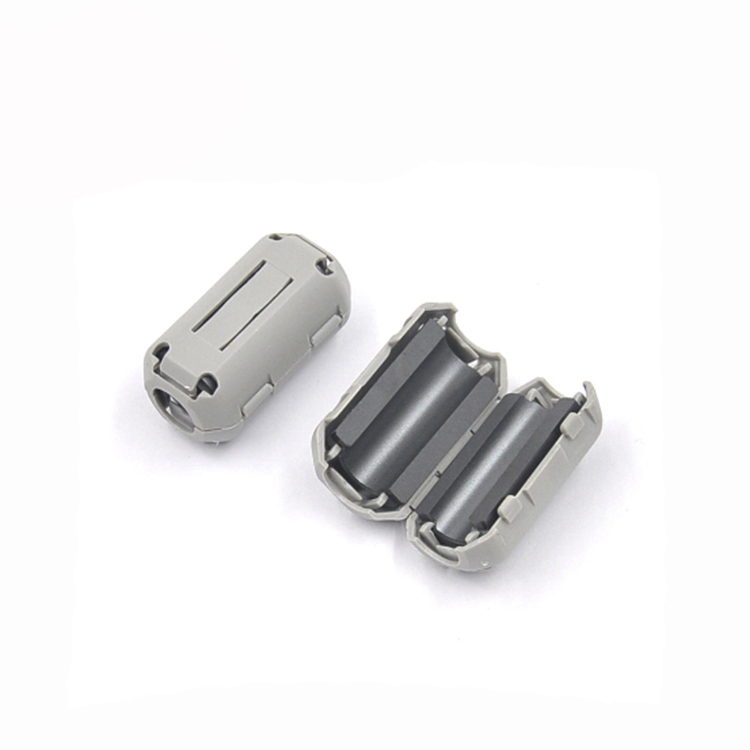
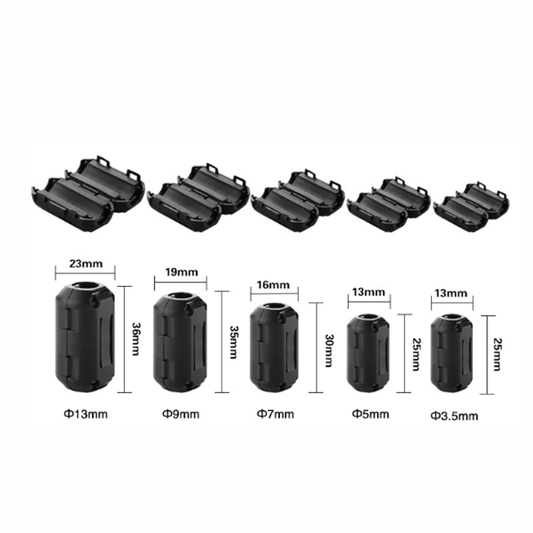
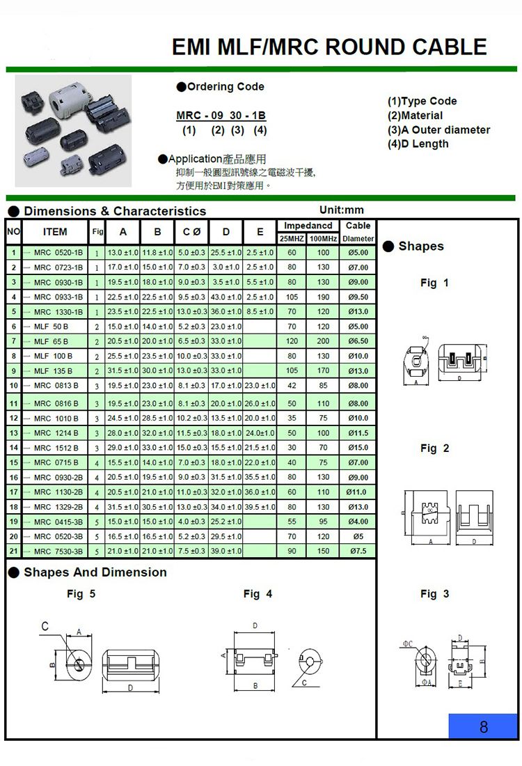
Speaking about installation, it’s a piece of cake! Simply clip a ferrite core to either end of the cable, about 10cm from the connections, and you’re done! These cores are intended for cables ranging in width from 3.5mm to 5.5mm; we also offer a bigger core for thicker cables.
I occasionally wish I could see electromagnetic waves. It would greatly simplify the detection of EMI. Instead of fiddling with sophisticated rigs and signal analyzers, I could just glance and understand what all the commotion was about. While we cannot see EMI, we may occasionally hear it as it passes through audio circuitry. A ferrite bead is one possible solution for this type of interference.
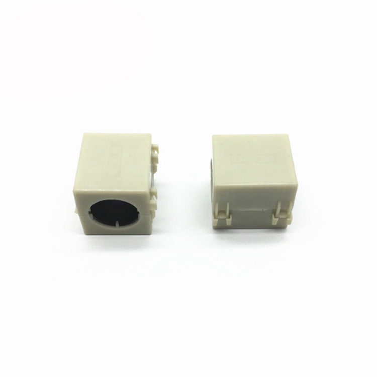
Unfortunately, ferrite beads (also known as a ferrite choke, ferrite clamp, ferrite collar, EMI filter bead, or ferrite ring filter) can be difficult to understand.
The ferrite core function is similar to that of an inductor, although the frequency response of the ferrite core deviates from this functionality at high frequencies. Furthermore, different kinds of beads, such as wirewound ferrite beads and chip ferrite beads, have varying noise reduction characteristics. Wirewound ferrite beads, for example, work across a wide frequency range yet provide less resistance in direct current configurations. To utilize them effectively, you must first understand their electromagnetic properties and how they change during usage. After you understand the physics behind ferrite bead applications, you may choose one on purpose for your circuit board. If you don’t, you risk producing more issues than you solve.