



Ferrite Ceramic Magnets
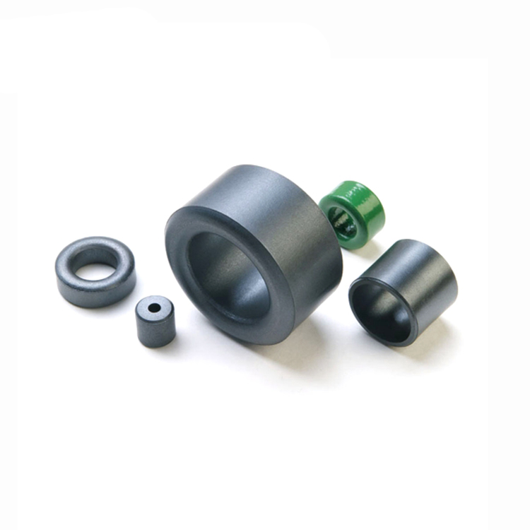
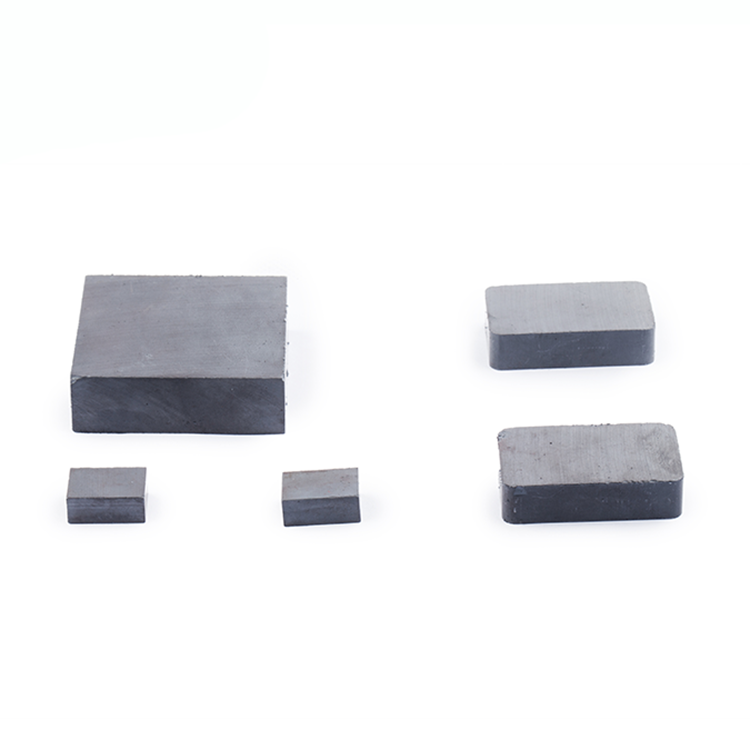
Ferrite ceramic magnets, also known as ceramic magnets or ferrite magnets, are permanent magnets made from a composite of iron oxide (Fe2O3) and strontium carbonate (SrCO3) or barium carbonate (BaCO3). They belong to the category of hard magnetic materials.
Here’s an analysis of ferrite ceramic magnets:
Chemical Composition: The primary constituents of ferrite ceramic magnets are iron oxide (Fe2O3) and either strontium carbonate (SrCO3) or barium carbonate (BaCO3). These materials are abundant and relatively low-cost compared to rare earth magnets like neodymium magnets.
Manufacturing Process: Ferrite ceramic magnets are typically produced through a powder metallurgy process. The raw materials, including iron oxide and the chosen carbonate, are mixed together and then compacted into the desired shape. The compacted magnets are then sintered at high temperatures, typically around 1200-1300°C, to form the final magnet.
Magnetic Properties: Ferrite ceramic magnets are characterized by their relatively low magnetic strength compared to rare earth magnets like neodymium magnets. However, they have good resistance to demagnetization and are highly stable under various environmental conditions, including high temperatures and corrosive environments.

The usage scenarios of NdFeB permanent magnets are roughly divided into adsorption, repulsion, induction, electromagnetic conversion, etc. In different applications, the requirements for magnetic fields are also different.
? The space structure of 3C products is extremely limited and requires high adsorption strength. The space structure does not allow the magnet size to increase, so the magnetic field strength needs to be increased through magnetic circuit design;
? In situations where magnetic field induction is required, excessively divergent magnetic lines of force will cause the Hall element to accidentally touch, and the magnetic field range needs to be controlled through magnetic circuit design;
? When one side of the magnet requires high adsorption strength and the other side needs to be shielded from the magnetic field, too high a magnetic field intensity on the shielding side will affect the use of electronic components. This problem also needs to be solved through magnetic circuit design;
? Occasions where precise positioning effect is required, occasions where uniform magnetic field is required…etc. In all the above situations, it is difficult to achieve the usage requirements using a single ferrite ceramic magnets, and when the price of rare earth is high, the volume and dosage of the magnet will seriously affect the cost and price of the product.
Therefore, When we meet the adsorption conditions or normal use, we can modify the magnetic circuit structure of the magnet to meet different usage scenarios, while reducing the amount of magnets to reduce costs.
Common magnetic circuits are roughly divided into HALBACH ARRAY, multi-pole magnetic circuits, focused magnetic circuits, added magnetic conductive materials ferrite ceramic magnets, flexible transmission, single-sided magnets, magnetic condensation structures, etc. Let me introduce them one by one for you: HALBACH ARRAY Halbach array This is an approximately ideal structure in engineering, with the goal of producing the strongest magnetic field using the smallest amount of magnets.
multi-pole magnetic circuit
Multi-pole magnetic circuits mainly utilize the characteristics of magnetic field lines to preferentially select the nearest different poles to form a magnetic circuit. Compared with ordinary single-pole magnets, the magnetic field lines (magnetic field) of multi-pole magnetic circuits are more concentrated on the surface, especially the more poles the more obvious it is ferrite ceramic magnets.
There are two types of multi-pole magnetic circuits, one is the multi-pole magnetization method of one magnet, and the other is the adsorption method of multiple unipolar magnets. The difference between these two methods is the cost, but the actual functions are the same. The advantages of multi-pole magnetic circuits in adsorption at small intervals are very obvious.
Focus on the magnetic circuit
The focusing magnetic circuit uses a special magnetic circuit direction to concentrate the magnetic field in a small area, making the magnetic field in this area very strong, even reaching 1T, which is very helpful for accurate positioning and local induction.
Magnetic material
Magnetic permeable materials use magnetic field loops to prioritize the path with the smallest magnetic resistance. Using highly permeable materials (SUS430, SPCC, DT4, etc.) in the magnetic circuit can well guide the direction of the magnetic field, thereby achieving local magnetization and isolation. Effect.
Flexible transmission
The characteristics of flexible transmission are that the attraction and repulsion formed by ferrite ceramic magnets achieve non-contact flexible transmission, small size, simple structure, torque can be changed according to the magnet volume and air gap size, and the adjustable space is large.
Single sided magnet
The characteristic of single-sided ferrite ceramic magnets is that the polarity of one side of the magnet is shielded and the polarity of the other side is retained. The direct adsorption force is strong, but the magnetic force attenuates greatly as the distance increases.
Magnetization structure
The form feature is that the ferrite ceramic magnets and the iron yoke are arranged relative to each other according to polarity. As the ratio of the thickness of the magnet to the thickness of the iron yoke increases, the thicker the thickness of the iron yoke, the smaller the divergence of the magnetic field lines. The magnetization structure can be flexibly designed according to the size of the air gap to achieve optimal results. It can effectively save magnets and the magnetic field is evenly distributed along the iron yoke. However, the disadvantage is that the assembly cost is high.
Do magnets with the same performance and volume have the same suction power?
The first thing that is certain is that the suction power is not the same. Which kind of suction force is the largest depends on the definition of the maximum magnetic energy product. When the working point of the magnet is near the maximum magnetic energy product, the magnet has the maximum working energy.
The adsorption force of the magnet is also a manifestation of work, so the corresponding suction force is also the largest ferrite ceramic magnets. What needs to be noted here is that the object to be attracted needs to be large enough and needs to completely cover the size of the magnetic pole, so that the material, size, shape and other factors of the object to be attracted can be ignored.
How to judge whether the working point of the magnet is at the maximum magnetic energy accumulation point. When the magnet is directly adsorbed to the material to be attracted, its adsorption force is determined by the air gap magnetic field and the size of the adsorption area.
Taking a cylindrical magnet as an example, when H/D≈0.6, its center Pc≈1, and when it is near the working point of the maximum magnetic energy product, the suction force is maximum.
This is also consistent with the rule that ferrite ceramic magnets are usually designed to have a relatively flat shape as adsorption parts. Taking the N35 D10*6 magnet as an example, FEA simulation can calculate that the suction force of the iron plate is about 27N, which is almost the maximum value of a magnet of the same volume and is 780 times its own weight.
Square ferrite ceramic magnets are similar to circular magnets. When directly adsorbed to the material to be attracted, the center Pc≈1, that is, near the maximum magnetic energy product operating point, the suction force will reach the maximum value of a magnet of the same volume, such as 10*10*6.5 or 15* 10*8.
Of course, the above is only the adsorption state of a single pole of the magnet. If it is multi-pole magnetization, the suction force will be completely different. The suction force of multi-pole magnetization will be much greater than that of unipolar magnetization (provided that the distance between the magnet and the adsorbed object is small).
Why does the suction force change so much after magnets of the same volume are made multi-pole magnetized? The reason is that the adsorption area S remains unchanged, but the magnetic flux density B value of the object to be attracted increases a lot. It can be seen from the magnetic field line diagram below, For multi-pole magnets, the density of magnetic field lines passing through the iron sheet is significantly increased. Still taking the N35 D10*6 magnet as an example, it is made bipolar magnetized ferrite ceramic magnets. The FEA simulated adsorption force of the iron plate is about 1100 times its own weight.
Since the ferrite ceramic magnets is made multi-pole and magnetized, each pole is equivalent to a more slender magnet, and its Pc value has changed. It can no longer be calculated based on the Pc value of the overall size, so its optimal size is no longer H/D≈ 0.6, but a flatter magnet. The specific size is related to the multi-pole magnetization method and the number of poles.
The more than ten elements of sintered NdFeB are just like the various seasonings we need to add to make a delicacy. It is precisely because of the scientific and regular combination of these elements with different intrinsic properties and functions that our NdFeB is made ferrite ceramic magnets. Boron comes in a variety of different grades and properties. Understanding the meaning of each element is of great significance for us to better understand the performance and manufacturing costs of different grades. Below we briefly introduce the value of these elements.
For easier understanding, we can divide the constituent elements of NdFeB into three categories:
◇ One is the main elements RE (Ce, Gd, Nd, Dy, etc.), Fe, B, which are mainly responsible for forming RE2Fe14B main phase grains.
◇ The second is small elements such as Al, Co, Ga, and Zr, which are mainly responsible for optimizing the coating of grain boundaries relative to main phase grains.
◇ Third, impurity elements, such as carbon, oxygen, etc., are inevitably introduced into raw materials and production.
A schematic diagram of the types of NdFeB elements is shown in the figure below.

Usually in the production process, in order to allow different formulas to exert better performance effects, we also need to conduct certain inspections and treatments on the raw materials before use to meet some basic requirements. The common requirements for some elements are as follows.
The above are typical reference values of commonly used raw materials. Actual raw material manufacturers often have certain deviations due to different process routes used in the production process. For example, the ratio of PrNd will change from 20:80 to 25:75, and GdFe will be less than 75. %, the B content in different batches of BFe will fluctuate greatly, which requires us to use it in combination with the actual content of each batch of quality inspection sheets during use.
Each element contained in NdFeB magnets has its own unique characteristics, such as:
◇ The introduction of La and Ce elements will reduce the remanence Br and coercive force Hcj of the magnet, but its price is very cheap and can reduce costs;
◇ REFeB composed of pure Nd element replacing PrNd has very high saturation magnetization and can be used to prepare ultra-high remanence ferrite ceramic magnets;
◇ The introduction of Tb element can greatly improve the Hcj of the magnet, but its cost is extremely expensive;
◇ The Gd element is relatively cheap. The REFeB formed by it has the highest Curie temperature and can prepare high-temperature resistant magnets, but it will significantly reduce Br.