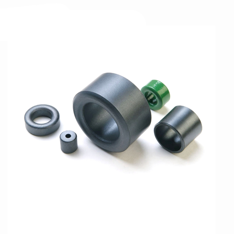
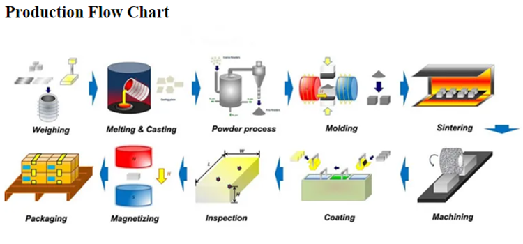
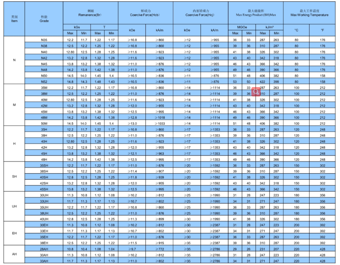
Applications of Neodymium Magnets in Magnetic MotorsApplications for neodymium magnets include electric vehicle motors. Neodymium magnets are used in every component of a hybridautomobile, from the DVD player engine to the wheels.The choice of a car magnet between samarium cobalt and neodymium is typically made based on the working temperature or corrosion resistance.Operating temperature:If heated above 176°F (80°C), a low coercivity grade Neodymium magnet may start to loose its power.Neodymium magnets of high coercivity grade have been created to operate with little irreversible loss at temps as high as 428°F (220°C).The need for low temperature coefficient in neodymium magnet uses has led to the development of a number of grades to satisfy particularworking needs.To evaluate the qualities of each category, please see our chart of magnetic properties.Neodymium magnets are susceptible to rust, particularly along a sintered magnet's grain limits.Serious degradation from this kind of rust can result, including the disintegration of a magnet into a powder of microscopic magneticparticles.In order to avoid exposure to the environment, a protective coating is added to handle this susceptibility.Although plating with other metals, polymer, and varnish protective layers, as well as nickel plating or two-layered copper-nickel plating, arealso options, they are less common.
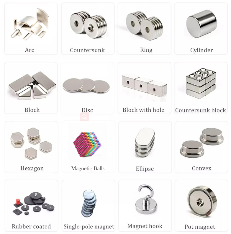
Disco, Cilindro, Bloque, Anillo, Avellanado, Segmento, Trapezoide y formas irregulares y más. Formas personalizadas disponibles
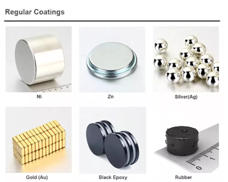
Revestimiento
Ni, Zn, Au, Ag, Epoxi, Pasivado, etc.
Aplicación
Sensores, motores, filtros de automóviles, soportes magnéticos, altavoces, generadores eólicos, equipos médicos, etc.
Muestra
Si está en stock, muestra gratuita y entrega el mismo día; si no está en stock, el plazo de entrega es el mismo que el de la producción en serie.
Magnets in a motor
Neodymium and Ferrite Motor Magnets Made in China China Rare Earth Magnet Limited manufacture motor magnets including sintered & bonded neodymium magnets , ferrite & ceramic magnets, alnico magnets, samarium cobalt magnets (smco) which can be used as rotor or stator in different permanent magnet motors such as electric motors, PM motors, AC motors, DC motors, Linear motors, Stepping motors, Brushless motors etc.
Sintered neodymium and SmCo magnets are the two most commonly used magnetic materials for motors. Neodymium magnets that have been sintered exhibit strong magnetic properties that can produce significant thrust for rotors and stators. The H, SH, EH, and UH lines of sintered NdFeB grades are well-liked because they can endure working temperatures of up to 100-200 degree C without losing magnetism.
However, since many motor types must operate at higher temperatures, SmCo magnets are favored due to their similar magnetic strength to sintered neodymium N35 grade and their maximum operating temperature range of 250–300 °C.
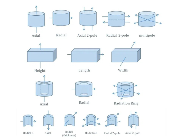
Bonded neodymium is used extensively in motors due to its versatility in terms of producible forms and magnetization directions. For instance, we created and magnetized a bonded NdFeB magnet with a diameter of 30 millimeters into 16 poles and 32 poles through width, which is impossible with any other sintered permanent magnetic substance.
China Rare Earth Magnet Limited can alter ferrite, alnico, and other fixed magnets for use in motors if clients so request.
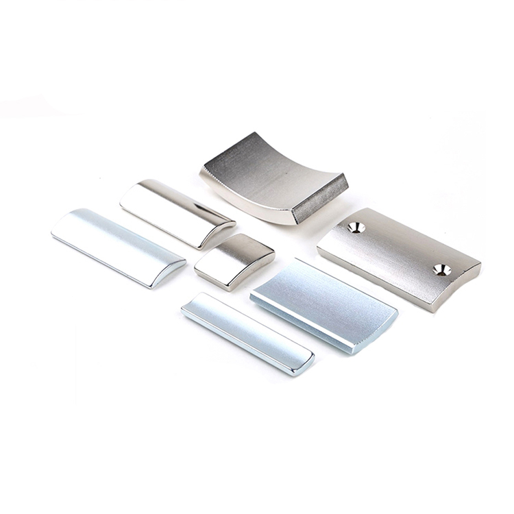
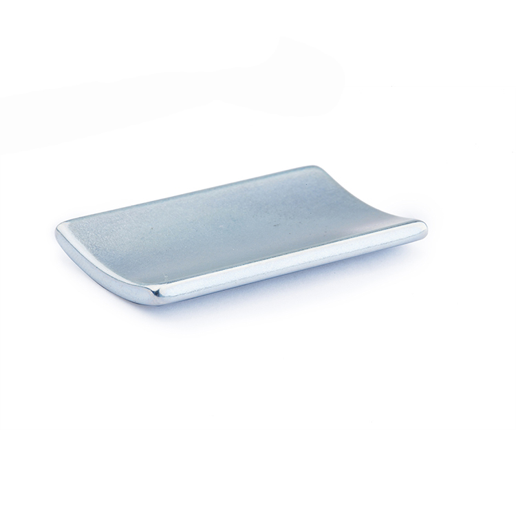
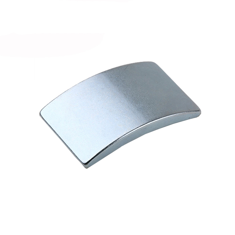
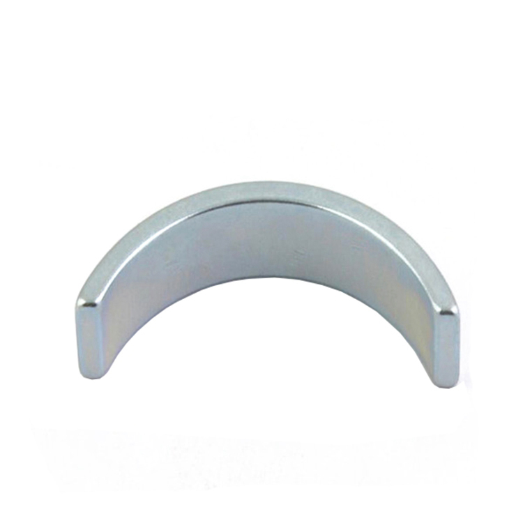
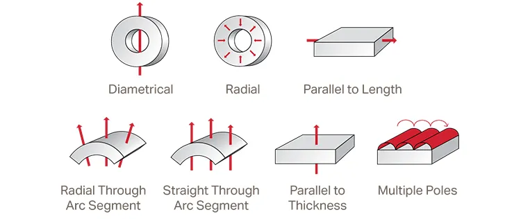
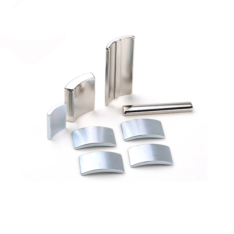
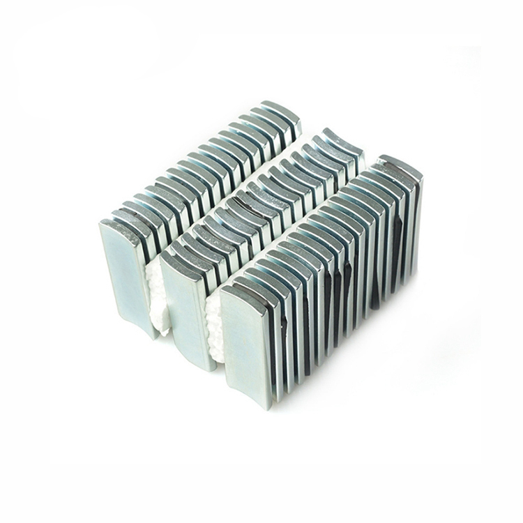
The most common motor magnet shapes and magnetization orientations are rings and arc segments magnetized through diameter. China Rare Earth Magnet Limited can provide a variety of motor magnet shapes, including block, disc, wedge, and heteromorphic shapes, depending on the specific requirements and drawings from customers.
NiCuNi, Zn, epoxy, phosphate, passivate, and other coatings are available.
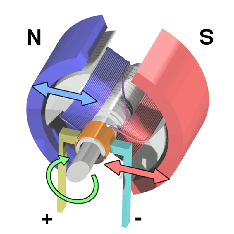
Engines with permanent magnets On the rotor of a synchronous machine, solid magnets composed of neodymium-boron-iron, samarium-cobalt, or ferrite may be used to create the magnetic field. These magnets are sometimes fixed in motors using adhesive so that the magnetic field is channeled radially across the air space. Other versions place the magnets in holes just below the surface of the rotor core or embed them into the surface. Another design of permanent-magnet motors uses radially positioned, circumferentially directed magnets to supply magnetic flux to iron poles, which in turn creates a radial field in the air space.
Permanent-magnet motors are primarily used in variable-speed drives, where the stator is powered by an electrically regulated source with changeable frequency and voltage. These drives have the ability to precisely regulate speed and location. They are also much more effective than induction motor drivers because there are no power losses in the rotor.
The operation of permanent magnet motors at synchronous speed from a source of steady voltage and frequency is possible. The damper winding is positioned in gaps in the rotor surface to provide beginning capability, and the magnets are inserted in the rotor iron. However, the rotor power factor cannot be controlled by such a generator.
Motors for hysteresis Synchronous motors are characterized by a special relationship between speed and supply frequency. Because of this, a number of unique kinds of synchronous motors have found widespread use in gadgets like clocks, cassette players, and phonographs. The hysteresis motor, whose rotor is made of a band of a semi-permanent magnet substance like high-carbon steel, is one of the most widely used. The motor runs as a permanent-magnet synchronous machine when it is running at maximum power. The stator field causes the rotor material to be cyclically magnetized around its hysteresis loop, resulting in a rotor field that lags the stator field by a few degrees and continues to generate torque if the speed is decreased by drawing the rotor out of synchronism.
These engines are extremely silent, have very little ripple, and offer excellent beginning power. Their uses are limited to low power ratings due to their poor efficiency. Engines with reluctance engine with reluctance in transverse section The idea behind how resistance motors work is that pressures are created that tend to align iron rods bearing magnetic flux with one another. The image depicts a transverse section of one type of reluctance motor. Four iron rods make up the rotor, which is devoid of any electrical windings. Each of the stator’s six points has a coil that carries electricity. In the scenario shown in the figure, coils a and a′ have just experienced current flow, causing a force on the rotor that aligns two of its poles with those of the a-a′ stator.
Coils a and a′ now have the current turned off, and coils b and b′ have it turned on. Two rotor poles are aligned with stator poles b and b′ as a result of the rotational force produced on the rotor. After that, coils a and a′ of the rotor are used before repeating the procedure with coils c and c′. The coil currents’ size determines the force, but their orientation has no bearing on it. By altering the sequence in which the coils are energized, the orientation of spinning can be altered. Other pole arrangements for reluctance motors include eight stator poles and six rotor poles.
Typically, semiconductor switches that link the stator coils to a direct voltage source regulate the currents in the coils. The switches are activated at the proper times using a signal from a location monitor that is placed on the motor shaft. The Hall effect-based magnetic monitor is frequently used. (The Hall effect involves the development of a transverse electric field in a semiconductor material when it carries a current and is placed in a magnetic field perpendicular to the current.) The entire apparatus is referred to as a self-synchronous motor drive. It can function at a variety of regulated speeds.
Another design for a reluctance motor uses a stator that resembles an induction motor and is powered by a three-phase adjustable source. Iron lengthwise laminations and nonmagnetic gaps make up the rotor. The laminations’ resistance to flux from the stator is much lower along them than it is across them.
Reluctance motors can be created to run at a fixed pace from a fixed frequency source. Salient rods on the rotor lack field windings. The three-phase winding of the circular rotor is reminiscent of an induction machine’s winding. The rotating surface of the machine has a damper winding installed so that it can commence as an induction motor. It functions as a synchronous motor once the rotor synchronizes with the stator’s spinning field.
Dirección magnética
Al acercarse o adherirse a algo, el imán descargará parte de la energía almacenada y, a continuación, almacenará o conservará la energía utilizada por la persona para alejarlo.
En sus extremos opuestos, cada imán tiene una cara que apunta al norte y otra que apunta al sur. La cara norte de un imán siempre estará orientada hacia el Sur.
Permanent magnet motors
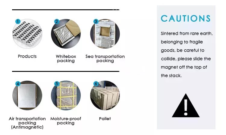
The triple nickel-copper-nickel covering on the magnets gives them a glossy metallic appearance and excellent rust resistance. Perfect for scientific experiments, small generator parts, and automotive parts. Hanlding Advice: Sintered material is used to create NdFeB magnets. The main characteristic is fragile. Please handle properly. Only Slide Off/On is possible. Do not place anything iron-containing near magnets or magnets. Don’t spill anything on a firm surface.
A variable frequency drive (VFD) is typically used to regulate the speed of ac motors. While a rotating magnetic field is frequently created by induction motors with stator windings and VFDs in many situations, precise speed control can also be achieved by using speed or position feedback devices as a reference to the VFD.
Without the use of feedback devices, comparable levels of speed control are sometimes feasible. The “high-frequency signal injection method” and a permanent magnet (PM) generator are used to accomplish this.
machinery with induction
An ac motor is another name for an ac induction generator (IM). The stator coil produces a spinning force. A current is produced in the rotor by the spinning field.
The turbine and magnetic field must move at different speeds in order to generate electricity. The propelling power is created by the field and current interacting. Ac induction devices are the most common motors used with variable speed drivers as a result.
engines PM An ac motor that employs magnets embedded in or affixed to the rotor’s surface is known as a PM motor. Instead of needing the stator field to create one by connecting to the rotor, as is the case with an induction motor, the magnets are used to create a continuous motor flux. The features of both motors are combined in a fourth motor called a line-start PM (LSPM) motor. An LSPM motor combines the magnets from a PM motor inside the cylinder with those from a squirrel cage motor.
Magnetic flux, flux connection, and flux It is crucial to first comprehend the ideas of magnetic flux, flux coupling, and magnetic flux in order to comprehend how PM motors work.
Flux: When current flows through a conduit, a magnetic field is produced. The velocity of movement of a property per unit space is defined by flux. The velocity of current movement through a specific conductor cross-section is known as the flux current.
Flux linkage: When a magnetic field reacts with a substance, as it does when a magnetic field passes through a coil of wire, flux linkage takes place. The quantity of windings and flux, where flux is the time-varying flux’s immediate value denoted by the symbol, define the flux linkage. The following are the criteria for flux coupling.
Permanent magnet dc motor
Magnetic flux: The pace at which a magnetic field passes through a specific conductor’s cross-section is known as magnetic flux. A permanent magnet inside or on the surface of a permanent magnet generator produces a magnetic flux field.
An inductor is a circuit component made up of a conducting wire, typically in the shape of a spiral. A continuous magnetic field will be produced by a conductor conveying a constant current. A straight relationship between a magnetic field and the current that created it can be shown. A adjacent conductor will experience a voltage change in response to a change in the magnetic field that is proportionate to the rate of change of the current that created the magnetic field. The following calculation determines the voltage in the conductor:
Inductance (L) is the proportionality constant that establishes the connection between the voltages induced by the rate at which the current changed over time to create a magnetic field. Inductance is the flux coupling per unit current, to put it simply. Inductance is an inactive component and solely a geometric feature, it must be made explicit. Weber-turns per ampere (or Henrys, or H) are units used to express inductance.
The d and q vectors are single-phase depictions of the flux produced by the three distinct sinusoidal phase variables moving at the same angular velocity, respectively. The field winding produces flow along the d axis, also referred to as the straight axis.
Torque is generated along the q line, also known as the quadrature axis. The quadrature axis will, by default, always be 90 degrees ahead of the direct axis electronically. Simply put, the major flux direction is along the d axis, and the main force generating direction is along the q axis.
Magnetic permeability: In electromagnetism, the capacity of a substance to sustain the creation of a magnetic field within itself is referred to as permeability. As a result, it refers to the level of magnetization that a substance acquires in reaction to an applied magnetic field.
There are several various motor models that can be used to depict a permanent magnet motor. The d-q motor paradigm is one of the most popular approaches.
PM motor d-axis and q-axis inductance: The inductances recorded as the flux path goes through the rotor in relation to the magnetic pole are known as the d-axis and q-axis inductances. The inductance that is detected when flux travels through the magnetic polarities is known as the d-axis inductance. The inductance measured when flow moves between the magnetic poles is known as the q-axis inductance.
The rotary flux connection between the d and q axes in an induction machine will be constant. The magnet in a permanent magnet machine, however, limits the amount of iron that can be used for flux coupling. The porosity of a magnet resembles that of air. Consequently, the magnet can be thought of as an air space.
The flux route passes through the magnet as it moves through the d plane. No magnets are encountered along the flux route that passes through the q plane. As a consequence, more iron can be connected to the q-axis flux route, increasing inductance. The q-axis inductance of a motor with an embedded magnet will be greater than the d-axis inductance. Due to the fact that surface-mount magnets are outside the rotor and do not restrict the quantity of iron linked by the stator field, a motor with these magnets will have almost equal q-axis and d-axis inductances.
Salience or saliency is the condition or trait by which something sticks out in relation to its surroundings.
The connection between the major flux-producing (d axis) and main torque-producing (q axis) inductances of the rotor is known as magnetic saliency. The greatest magnetic saliency is at 90 electrical degrees from the primary flux axis (d axis), but it changes based on where the rotor is in relation to the stator field. (see Figure 1).
The current in the stator windings necessary to produce magnetic flow in the rotor center is known as excitation current. Because a permanent magnet motor’s magnets already produce an existing magnetic field, permanent magnet motors do not require excitation current in the stator circuit.
The current needed to produce engine traction is referred to as secondary current, also known as “the torque-producing current.” Torque-producing currents make up the bulk of the currents in a permanent magnet generator.
Precios de los imanes Ndfeb
Pull-in current: Unlike an amplifier and servo matched combination built for motion control, a typical VFD does not know the location of the motor’s rotor magnetic pole. A field cannot be generated in the stator to improve torque generation unless the magnetic pole position is known. A VFD may therefore provide dc power to lock the magnetic field into a certain point. The “pull-in current” is the amount of current required to bring the rotor into the circuit.
High frequency injection is an inverter technique used to determine the magnetic pole position of a permanent magnet motor. The process is initiated by the inverter sending a high-frequency, low-voltage pulse down any channel into the motor. The inverter then changes the stimulation angle.
Rotor impedance varies with input position. The inner permanent magnet motor terminal resistance decreases when the magnetic pole axis (d-axis) and the high-frequency signal injection axis are parallel, or at 0 degrees. Maximum resistance exists at 90 degrees. The drive may leverage this functionality to determine the rotor location without using pulse encoders by injecting high frequency ac voltage/current into the IPM motor. Furthermore, because the motor’s back-emf voltage level is too low, full-load torque management is typically difficult in the low-speed area. The high-frequency signal injection approach can be utilized in this scenario to assess speed in this region.
Back-emf waveform The counter-electromotive force is also known as back emf, which is an abbreviation for reverse electromotive force. The reverse electromotive force is the energy that emerges in electric motors when the magnetic fields of the rotor and stator move relative to one another. The structure of the back-emf waveform is determined by the geometrical properties of the rotor. Triangle, sinusoidal, trapezoidal, or any combination of these patterns can be used.
Back-emf waves are produced by both PM and induction devices. The lack of a stator field in an induction machine causes the residual rotor field to progressively fall, causing the back-emf waveform to degenerate. However, with a PM machine, the motor generates its own magnetic field.
As a result, everytime the rotor rotates, a charge can accumulate in the stator windings. The back-emf voltage, which increases linearly with speed, is an important factor in determining the maximum operating speed.
identifying machine force in PM Magnetic torque and reluctance torque are the two components of an electronic machine’s traction. The “force acting on the magnetic material that tends to align with the main flux in order to minimize reluctance” is referred to as reluctance torque. The force produced when the rotor axis is aligned with the stator flux field is referred to as reluctance torque. Magnetic force is produced by the interaction of the magnet’s flux field with the current in the stator winding.
Reluctance torque: The force generated is known as reluctance torque.
by pushing a desired straight movement from the north stator pole to the south stator pole, resulting in rotor alignment.
Permanent magnets generate a flux field in the rotor, resulting in magnetic torque. The magnetic field of the rotor and the field created by the stator merge. When the orientation of the stator field in reference to the rotor field changes, the rotor shifts. The magnetic torque is the result of this interaction.
The two main types of PM motors are surface permanent magnet motors (SPM) and internal permanent magnet motors (IPM). Figure 3 depicts this. Both types of engines do not have rotor rods. Because of the solid magnets inside or linked to them, both types generate magnetic flux.
SPM motor magnets are mounted to the rotor’s outside surface. Because of this mechanical connection, their mechanical strength is lower than that of IPM motors. The lower mechanical strength limits the motor’s maximum safe mechanical speed. In addition, these motors have exceptionally low magnetic saliency (Ld Lq).
Inductance values measured at the rotor terminals are constant regardless of rotor orientation. Due to the close proximity of the saliency ratio to one, SPM motor designs rely largely, if not totally, on the magnetic torque component to provide traction.
The permanent magnet is really a component of the rotor in IPM motors. IPM motors are substantially more mechanically sound than SPM motors and can function at extremely high velocities due to the placement of the permanent magnets.
These motors are further identified by a rather high magnetic saliency ratio (Lq > Ld). Because of their magnetic saliency, the magnetic and reluctance torque components of an IPM motor may create torque. Figure 4 depicts this.
PM drive systems There are two types of PM motor designs: external and interior. Within each group, there are subcategories. Magnets in a surface PM motor can be positioned on or recessed into the rotor’s surface to increase the design’s durability. An inside permanent magnet generator’s placement and construction might vary substantially. The IPM motor’s magnets can be installed as a single large block or staggered as they approach the center.
As an alternative, they might be incorporated into a spoke design.
Capacitance of the PM motor varies with load The amount of flux that can be linked to a ferrous item to create torque is limited.
The iron will ultimately get saturated and no longer enable flux to attach to it. As a result, the inductance of a flux field’s path is reduced. As the load current increases, the d-axis and q-axis inductance values in a PM machine drop.
The axial inductances of an SPM motor are fairly comparable. Because the magnet is external to the rotor, the q axis inductance will decrease at the same rate as the d axis inductance.
The inductance of an IPM motor, on the other hand, decreases differently. Because the magnet is in the flux path and does not provide an inductive property, the d-axis inductance is less by definition.
The flux drop with respect to the q axis is considerably decreased since there is less iron to saturate in the d axis.
PM motor flux deterioration/intensification Flux is produced by the magnets in a permanent magnet generator. A given flux field path can be either boosted or resisted. By boosting or raising the flux field, the engine will be able to temporarily increase torque output. By opposing the flux field, the current magnet field of the motor will be abolished.
When the back-emf voltage is reduced, the magnet field is reduced, limiting the amount of force produced. Lowering the back-emf voltage frees up more energy to run the motor at higher output rates. In both circumstances, more electricity is required to run the equipment.
The motor controller’s providing of the motor current’s course across the d axis determines the anticipated output.
The angle of stimulation The angle of excitation is defined as the vector sum of the d-axis and q-axis waveforms stimulated to the actuator with respect to the d axis. The magnet is always observed to be parallel to the d plane. The largest magnetic flux is observed on the q axis, which is 90 electronic degrees from the d axis.
As a result, the majority of sources for excitation angle already account for the 90-degree fluctuation between the d and q axes.
torque as well as phase ratio Magnetic force is greatest when the stator field excites the motor rotor 90 electrical degrees from the d axis. (Position of the motor magnet). Resistance torque, which peaks 45 electrical degrees past the q line, takes a different path. The maximum magnetic torque makes advantage of both the engine’s magnetic and reluctance torques. Moving away from the q axis reduces magnetic toque, but the increase in resistance torque more than compensates. The highest combined magnetic and reluctance torque occurs at around 45 electrical degrees from the q axis, however the exact angle depends on the characteristics.
IPM actuator power efficiency How much power a PM motor can produce is determined by the configuration of the motor magnets and the resulting motor saliency. Motors having a high saliency ratio (Lq > Ld) can produce more power and function more effectively by using the motor’s reluctance torque. An inverter can be used to modify the angle of stimulation with respect to the d axis to increase the magnetic and reluctance torques of the motor.
PM motor magnets of various types There aren’t many magnet materials that are stable enough to be employed in electric engines today. Each metal has advantages and disadvantages.
Permanent magnet demagnetization Persistent magnets have several limits, despite the fact that they are rarely long-lasting. Specific pressures can be used to demagnetize these materials.
Permanent magnet motors
In other words, the magnetic qualities of the permanent magnet material may be removed. A persistent magnetic material may lose its magnetic characteristics if subjected to tremendous strain, high temperatures, or a significant electrical disturbance.
To begin, physical means are often utilized to apply pressure on a permanent magnet. If a magnetic material is subjected to violent collisions or falls, it may weaken or even become demagnetized. Magnetic characteristics are inherent in ferrous substances. These magnetic properties, on the other hand, can radiate in a wide variety of directions. One way of magnetizing ferromagnetic materials is to apply a strong magnetic field to the substance in order to align its magnetic dipoles. The alignment of these dipoles restricts the magnetic field of the material to a certain solution.
After a violent collision, the magnetic domains of the material might lose their atomic alignment, reducing the expected strength of the magnetic field.
Second, climate can have an effect on a stationary magnet. Temperature fluctuations cause agitation of the magnetic components of a stationary magnet. Magnetic dipoles can survive a certain amount of temperature turbulence. Even at ambient temperature, continuous movement can limit the power of a magnet. All magnetic materials have a “Curie temperature,” which determines the temperature at which the substance entirely demagnetizes as a result of thermal agitation. Magnetic materials’ ability to retain their strength is defined using terms such as coercivity and retentivity.