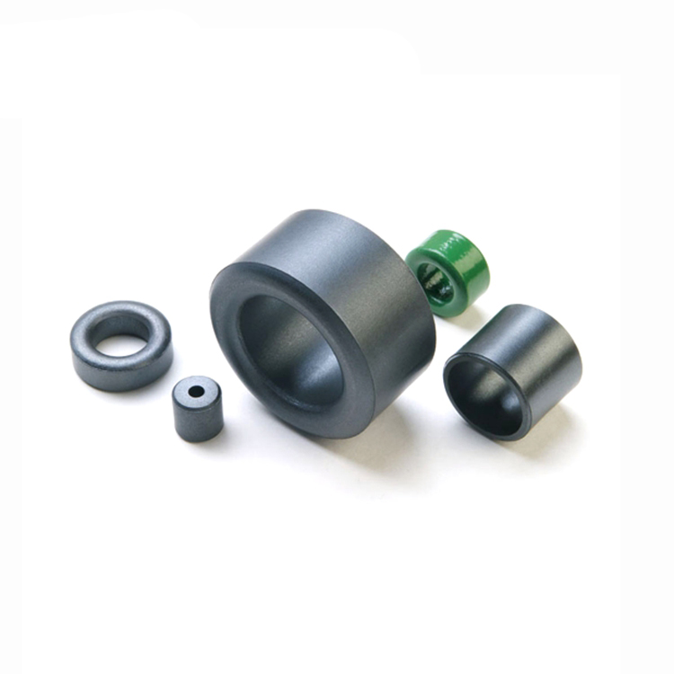
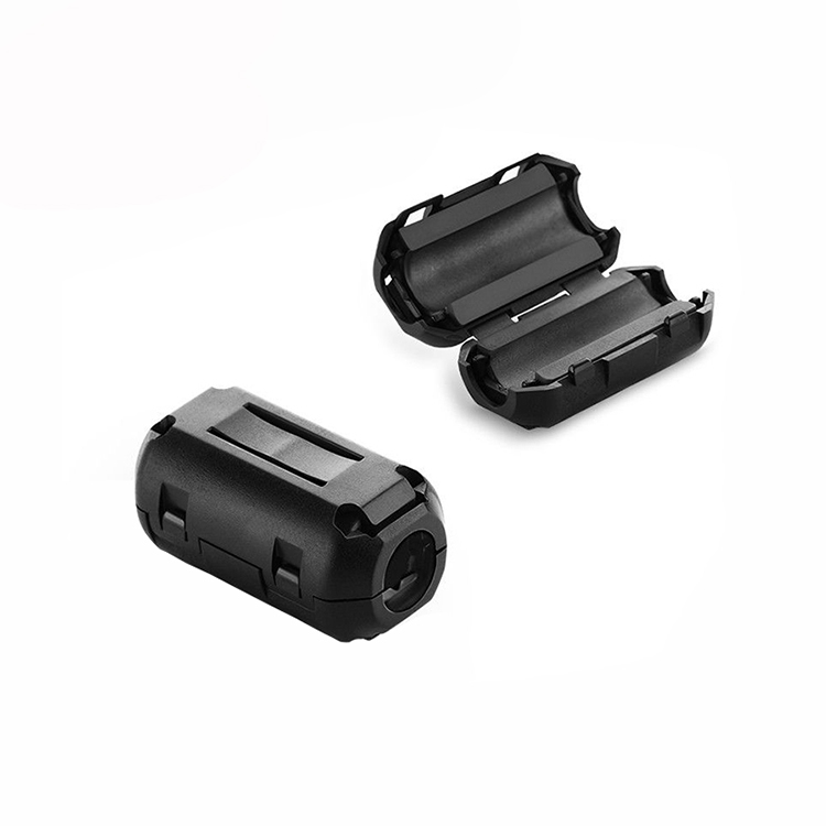
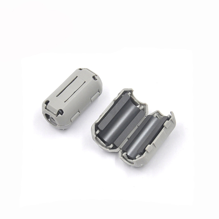
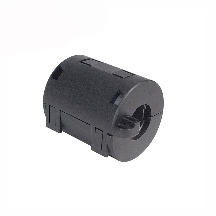
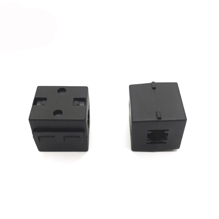
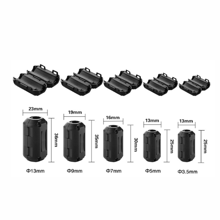
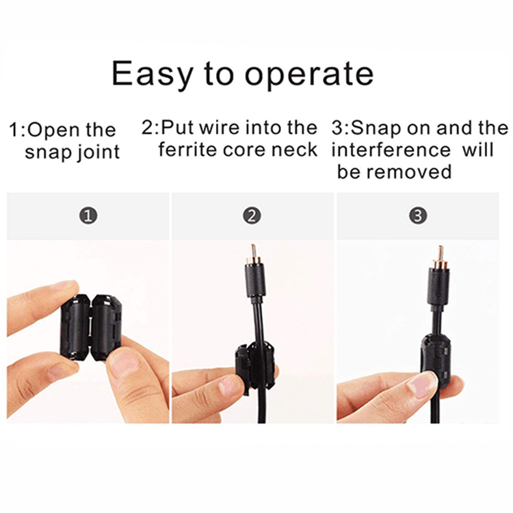
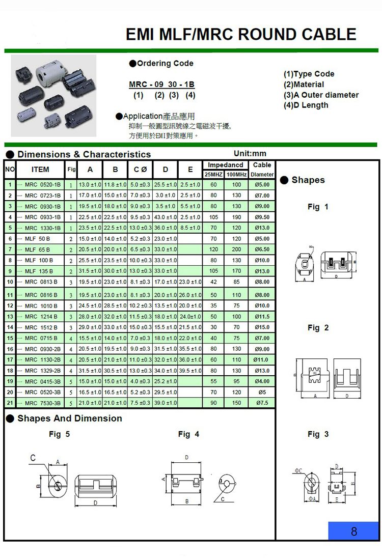
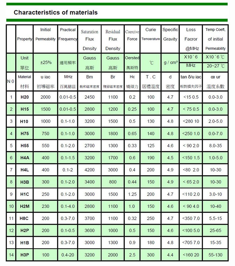
Electric transformers and inductors frequently use ferrite cores, which are magnetic centers. They come in a range of sizes and forms and are made of ceramic materials. Due to their high magnetic permeability, low conductivity, and capacity to decrease high-frequency losses, ferrite cores are useful for lowering noise levels and common mode currents in electrical equipment.
We’ll look at how ferrite cores successfully reduce EMI in wires in this blog post.
Why are ferrite cores used in cables to suppress EMI?
Electronic gadgets employ ferrite centers to reduce noise. They are an efficient method to reduce common mode current and radiation by incorporating high-frequency resistance into a wire. They are typically found in keyboards, mice, and computer connections.
When a gadget is fueled by an external transformer or another source, power supply lines also use ferrite cores.
The cable’s conducted and/or emitted radiation are reduced by the core, which functions as a common mode choke. Additionally, they aid in reducing high-frequency wire snagging. Ferrite cores essentially function as high-frequency resistors with zero resistance in direct current or at low frequencies.
They play a particularly important role in attenuating over 10MHz undesirable noise transmissions. However, because of their relatively low impedance at these frequencies, they are not very helpful for low-frequency cable transmissions, which are those below 10 MHz. Multiple turns can be used to raise the resistance of ferrite cores, but doing so reduces the high-frequency performance of the cores and increases interwinding capacitance.
Ferrite core specifications and significance
According to their composition and structure, ferrite centers function differently when it comes to filtering out electromagnetic interference. The reason for this is that because the magnetic permeability varies depending on the components, so does the resistance.
They are particularly important for attenuating undesirable noise transmissions above 10MHz. They are less helpful for low-frequency cable leaks, below 10 MHz, though, as their impedance is too low to function at these frequencies. Multiple turns can raise the resistance of ferrite cores, but doing so causes the interwinding capacitance to rise and the high-frequency performance of the cores to suffer.
Ferrite core characteristics and significance
Depending on the materials and shapes used, ferrite centers function differently in terms of reducing electromagnetic interference. Due to the fact that various materials have varying magnetic permeabilities and thus different impedances.
Utilizing ferrite materials also affects the relationship between the reactance and resistance components. The characteristics of ferrite centers.
Therefore, there won’t be any inductance or resistance if there is no magnetic field.
An inductor is created by attaching the wire to the ferrite center in order to reduce the common-mode current. As a result, any current will cause the core to generate a magnetic field similar to that of an inductor. As a result, you gain the benefit of both rising frequency and raising impedance.
Common mode choke is the mechanism, which exhibits a high resistance to common mode currents and a low impedance to differential mode currents. The choke’s high resistance stops the emergence of common mode currents. Due to the minimal losses of the ferrite cores used for this, common mode volts are converted to heat inside the cores.
The common mode current in cables and wire assemblies is the main source of breakdowns. This current may also return via a different path, such as a ground plane, a nearby wire, or any other unforeseen path. In a circuit, common mode currents take the path of least resistance.
الخاتمة
For the purpose of reducing noise in wires, ferrite centers are the ideal option. Power supply cables benefit from them, which makes them perfect for a variety of electrical needs and helps to improve their performance. For the purpose of preventing issues with electromagnetic emission in wires, Cosmo Ferrites makes ferrite cores of the highest quality. You can ask our team for advice if you want to learn more about their efficiency and how they use your application.
What Is a Ferrite Bead and How Do They Work?
Ferrite beads are passive electrical components that are capable of suppressing high frequency signals on a power supply line. They are often put around a power/ground line pair that is inbound to a specific device, such as your laptop’s power cord. The magnetic core surrounding a conductor causes a back EMF in the presence of a high frequency signal, essentially attenuating the ferrite frequency response, according to Faraday’s Law. Standard ferrite beads are available from specialized producers like as Coilcraft, however some tasks may necessitate bespoke beads.
Ferrites are magnetic materials that, when placed in a ferrite clamp around a power supply/ground line, offer a source of inductive impedance for signals travelling through the line. This may lead you to believe that they are simple inductors, but they are not. A ferrite bead, in actuality, is a nonlinear component; the impedance it supplies changes as the load current and voltage drop over the ferrite alter. A ferrite bead’s simplified circuit model can help you grasp its frequency characteristics. However, take in mind that these characteristics might alter depending on current and temperature.
What Purposes Do Ferrite Beads Serve?
Because ferrite bead impedance is inductive, ferrite bead inductors are employed in electronic components to attenuate high-frequency signals. When a ferrite bead choke is connected to a power line that connects to an electronic equipment, it reduces any spurious high frequency noise that may be present on the power connection or output from a DC power source. This ferrite clamp use is one of several approaches to noise reduction, such as that used by a switched-mode power supply. This method of using ferrite beads as a ferrite filter suppresses and eliminates transmitted EMI.
An EMI filter bead/power supply filter bead is often rated for a specific DC current threshold, which is one of the many applications for ferrite beads as filters. Currents that exceed the specified value might cause harm to the component. The problem is that heat has a significant impact on this limit. The rated current rapidly drops as the temperature rises. The ferrite’s impedance is also affected by the rated current. A ferrite bead will “saturate” and lose inductance as the DC current rises. Saturation can lower the ferrite bead impedance by up to 90% at reasonably large currents.
Inductor vs Ferrite Bead
Although a ferrite bead may be treated as an inductor, ferrite bead inductors do not act normally. To compare the behavior of a ferrite bead to that of an inductor, transmit an analog signal through the bead and sweep the frequency through multiple orders of magnitude. If you plot the frequency-swept data for a ferrite bead on a Bode plot, you’ll notice that the ferrite bead has a sharper roll-off at higher frequencies than an inductor with identical low frequency characteristics.
In parallel with an RLC network coupled with a series resistor, a ferrite bead may be represented as capacitors and inductors, as well as a resistor. The series resistor measures the device’s resistance to direct current (DC). In this concept, the inductor represents a ferrite bead with the primary purpose of attenuating high-frequency signals, i.e., producing inductive impedance via Faraday’s Law. In this model, the parallel resistor compensates for eddy current losses caused within the ferrite bead at high frequencies. Finally, in this approach, the capacitor compensates for the component’s intrinsic parasitic capacitance.
A ferrite bead impedance curve shows that the predominantly resistive impedance is extraordinarily high in only a tiny band. Within this narrow area, the bead’s inductance is dominant. At higher frequencies, the ferrite bead impedance becomes capacitive over and rapidly diminishes. As frequency increases, the capacitive impedance decreases to a very tiny value, and the ferrite bead impedance seems totally resistive.
Now that you’ve mastered the ferrite principle, it’s time to select one for your gadget. This is not difficult, and if you want to know how to pick a ferrite bead for a design, you simply need to pay attention to the specs of the bead. You may be asking if ferrite beads are required for my design. The solution, like many technical decisions, is not that easy. If you know your board will encounter conducted EMI within a certain frequency range and need to attenuate these frequencies, a ferrite bead may be the correct solution for your design.
Without more thought, it is simple to assume that ferrite beads “attenuate high frequencies” based on their inductive activity. However, ferrite beads can not function as a broad low-pass filter since they can only attenuate a narrow range of frequencies. You must pick a ferrite bead and choke where your unwanted frequencies are in the resistive band. If you go too low or too high, the bead will not have the desired impact.
Before choosing a certain ferrite bead for your design, check with the manufacturer to see if they can offer you with impedance vs. load current curves for the ferrite bead. By far the greatest tool to utilize if you’re not sure how to choose a ferrite bead. If your load currents are really high, you must choose a ferrite bead that can tolerate them without saturating and losing impedance within the acceptable frequency range.